Plus 2.X:Building: Unterschied zwischen den Versionen
Krizzl (Diskussion | Beiträge) |
SebSta (Diskussion | Beiträge) |
||
| (10 dazwischenliegende Versionen von einem anderen Benutzer werden nicht angezeigt) | |||
| Zeile 4: | Zeile 4: | ||
For the new project, the building can be created in two ways. Is the building or the space not too complex in its geometry the [[Plus 2.X:Building_Wizard| automatic building wizard]] can be used to generate. This tool generates the building with some details of floor plan, roof form and foundation . | For the new project, the building can be created in two ways. Is the building or the space not too complex in its geometry the [[Plus 2.X:Building_Wizard| automatic building wizard]] can be used to generate it. This tool generates the building with some details of floor plan, roof form and foundation . | ||
[[Bild:P2-Building_Wizard.png|left]] | [[Bild:P2-Building_Wizard.png|left]] | ||
<br style="clear:both;" clear="all" /> | <br style="clear:both;" clear="all" /> | ||
| Zeile 14: | Zeile 14: | ||
[[Bild:WUFI-PlusVertices.jpg|700px]] <br> | [[Bild:WUFI-PlusVertices.jpg|700px]] <br> | ||
<br style="clear:both;" clear="all" /> | <br style="clear:both;" clear="all" /> | ||
It is advisable to expand the visualization box using the [[Plus 2.X:Visualization_Box|Expand/Shrink Button]] | It is advisable to first expand the visualization box using the [[Plus 2.X:Visualization_Box|Expand/Shrink Button]], and also [[Plus 2.X:Visualization_Box|vertices]] must be switched visible. | ||
If entering a building using the Edit 3D Option, make sure to use internal measurements. | |||
== General Operations == | == General Operations == | ||
| Zeile 34: | Zeile 35: | ||
'''"Make Component of selelected Vertices"'''creates a component of all selectes vertices, but only if all are in the same plane. The vertices should be selected counter clockwise around the future component to make sure the normal vector points to the outer side of the component.<br> | '''"Make Component of selelected Vertices"'''creates a component of all selectes vertices, but only if all are in the same plane. The vertices should be selected counter clockwise around the future component to make sure the normal vector points to the outer side of the component.<br> | ||
<br style="clear:both;" clear="all" /> | <br style="clear:both;" clear="all" /> | ||
== Two Point Operations == | == Two Point Operations == | ||
| Zeile 55: | Zeile 55: | ||
'''"Change Orientation (inner<->outer)"''' changes the orientation (and the direction in which the normal vector points).<br> ZONES | '''"Change Orientation (inner<->outer)"''' changes the orientation (and the direction in which the normal vector points).<br> ZONES | ||
'''"Ungroup"''': Ungrouping components means to separate one or more components from their "Group". Components which probably have the same construction, for example exterior walls are automatically grouped if "Group Components" is tagged in the [[Plus 2.X:Building_Wizard|Building Wizard]]. However, one ore more components can be ungrouped again if they are supposed to be edited separately. There are two possible actions: '''"Ungroup main component"''', which has the effect, that only the red-marked component is ungrouped from the rest of the components or '''"Ungroup all components"''' which ungroups all selected components. Ungrouped components are individually selectable and appear in the [[Plus 2.X:Tree|Navigation Tree]].<br> | '''"Ungroup"''': Ungrouping components means to separate one or more components from their "Group". Components which probably have the same construction, for example exterior walls are automatically grouped if "Group Components" is tagged in the [[Plus 2.X:Building_Wizard|Building Wizard]]. However, one ore more components can be ungrouped again if they are supposed to be edited separately. There are two possible actions: '''"Ungroup main component"''', which has the effect, that only the red-marked component is ungrouped from the rest of the components or '''"Ungroup all components"''' which ungroups all selected components. Ungrouped components are individually selectable and appear in the [[Plus 2.X:Tree|Navigation Tree]].<br> | ||
'''"New Copy/Move Component"''' copies the selected component(s) and moves them along inputted coordinates. There | '''"New Copy/Move Component"''' copies the selected component(s) and moves them along inputted coordinates. There again are two different actions, "New Copy/Move main Component" which only copies and moves the red-selected component and "New Copy/Move all Components" which has the effect that all selected components are copied and moved.<br> | ||
'''"Create Component(s) on Border"''' allows to create new component(s) along the border of the selected component(s) whose direction can be entered individually. <br> | '''"Create Component(s) on Border"''' allows to create new component(s) along the border of the selected component(s) whose direction can be entered individually. <br> | ||
'''"Expand/Shrink Component"''' lets the user enter a factor for expanding or shrinking the selected component(s). <br> | '''"Expand/Shrink Component"''' lets the user enter a factor for expanding or shrinking the selected component(s). <br> | ||
'''"Delete selected Components/(s)"''' erases all selected components. | '''"Delete selected Components/(s)"''' erases all selected components. | ||
==Movies== | |||
Watch these two movies to see how exemplary buildings are created using the 3D tools. | |||
*This [http://www.wufi-wiki.com/wufifilme/step3_geometry/step3_Building_Geometry.htm '''movie'''] belongs to the [[Plus 2.X:Input|second example]] that can be found in the tutorial. | |||
*This movie shows the 3D tools using the example of a [http://www.wufi-wiki.com/wufifilme/rest/cube/r_cube.htm '''cube'''] | |||
Aktuelle Version vom 11. Juni 2013, 12:58 Uhr
There are two possibilities of generating a building.
Building Wizard
For the new project, the building can be created in two ways. Is the building or the space not too complex in its geometry the automatic building wizard can be used to generate it. This tool generates the building with some details of floor plan, roof form and foundation .
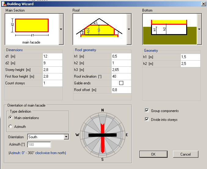
Note, that of course, all values entered are internal measurements.
Edit 3D
If the geometry of the building exceeds the capabilities of the Building Wizards, it can be expanded and changed in the Visualization Box. Also new Buildings can be created using vertices and connecting them to components. This allows the input of complex building shapes.
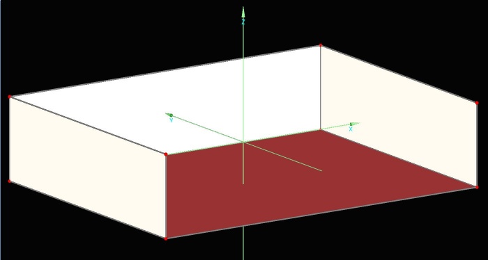
It is advisable to first expand the visualization box using the Expand/Shrink Button, and also vertices must be switched visible.
If entering a building using the Edit 3D Option, make sure to use internal measurements.
General Operations
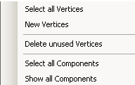
New vertices can be defined by right clicking into the Visualization Box and choosing "New Vertices" and then entering the coordinates.
Right clicking into the Visualization Box also allows you to choose from "Select all Vertices", "Delete unused Vertices" (unused means not in contact with any components), "Select all Components" and "Show all Components" (for example to change from viewing only one zone to viewing the whole building again)
Vertices Operations
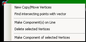
The vertices are arbitrarily variable with different operations who are invoked for selected vertices by a right mouse click on them. Multiple vertices can be selected by holding CTRL.
"New Copy/Move Vertices" copys selected vertices and moves this copied vertices alongside the entered coordinates.
"Find intersecting Points with Vector" (...)
"Make Component(s) on Line" allows to create new components along the border of the plane formed by the selected vertices. The orientation and size of these has to be entered via a vector. This operation is of course only possible if several vertices are selected.
"Delete selected Vertices" is another possible operation.
"Make Component of selelected Vertices"creates a component of all selectes vertices, but only if all are in the same plane. The vertices should be selected counter clockwise around the future component to make sure the normal vector points to the outer side of the component.
Two Point Operations
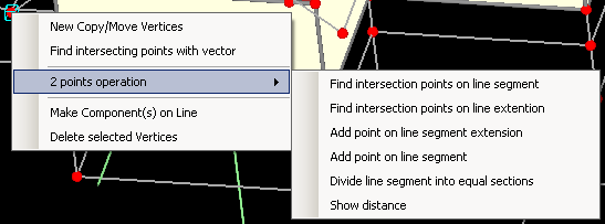
"Find intersection Points on Line" selects all vertices on the line between the two selected vertices.
"Find intersection points on line extension" selects all vertices on the line cutting through the two selected vertices.
"Add point on line segment extension" extends the line between the two points by an optional value and puts a new vertice at the end of that line. The line starts at the point, that is selected first and the extension begins at the point that is selected second.
"Add point on line segment" adds a new vertice on the line between the two points, the difference to the above mentioned operation is that the entered value for the distance means the distance of the new vertice from the vertice that is selected first.
"Divide line segment into equal sections" allows parting the line between two vertices into arbitrary sections. New verices are created at the end of every section.
"Show distance" outputs the exact distance between the two selected vertices.
Component Operations
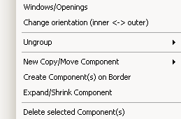
Also components can be edited. Right clicking on a selected component makes several operations possible. Several components can be selected by holding CTRL.
"Properties" opens the Properties Window of a component.
"Windows/Openings" opens the Component Openings Window.
"Change Orientation (inner<->outer)" changes the orientation (and the direction in which the normal vector points).
ZONES
"Ungroup": Ungrouping components means to separate one or more components from their "Group". Components which probably have the same construction, for example exterior walls are automatically grouped if "Group Components" is tagged in the Building Wizard. However, one ore more components can be ungrouped again if they are supposed to be edited separately. There are two possible actions: "Ungroup main component", which has the effect, that only the red-marked component is ungrouped from the rest of the components or "Ungroup all components" which ungroups all selected components. Ungrouped components are individually selectable and appear in the Navigation Tree.
"New Copy/Move Component" copies the selected component(s) and moves them along inputted coordinates. There again are two different actions, "New Copy/Move main Component" which only copies and moves the red-selected component and "New Copy/Move all Components" which has the effect that all selected components are copied and moved.
"Create Component(s) on Border" allows to create new component(s) along the border of the selected component(s) whose direction can be entered individually.
"Expand/Shrink Component" lets the user enter a factor for expanding or shrinking the selected component(s).
"Delete selected Components/(s)" erases all selected components.
Movies
Watch these two movies to see how exemplary buildings are created using the 3D tools.
- This movie belongs to the second example that can be found in the tutorial.
- This movie shows the 3D tools using the example of a cube