Plus:TreeHeatedSpace: Unterschied zwischen den Versionen
Tes (Diskussion | Beiträge) |
Tes (Diskussion | Beiträge) |
||
| (38 dazwischenliegende Versionen desselben Benutzers werden nicht angezeigt) | |||
| Zeile 6: | Zeile 6: | ||
[[Bild:WUFI-PlusTreeComponents.jpg|thumb]] | [[Bild:WUFI-PlusTreeComponents.jpg|thumb]] | ||
When the project building is edited | When the project building is edited with the Building Wizard or by Script file all componets are listed in the Components/Geometry elemtent. The area, the orientation and inclination are indicated. | ||
The components are arranged by stories and orientation in the Navigation Tree and can be selected here for entering the necessary inputs. | The components are arranged by stories and orientation in the Navigation Tree and can be selected here with a double click for entering the necessary inputs. | ||
<br style="clear:both" /> | <br style="clear:both" /> | ||
===Single Component=== | ===Single Component=== | ||
| Zeile 23: | Zeile 23: | ||
The geometry of the window can be edited easy by defining position and dimension. | The geometry of the window can be edited easy by defining position and dimension. | ||
Then the window is to assign with the according window type. | Then the window is to assign with the according window type. A few window types are already default but can be changed easy. Or a new window type can be defined. | ||
In tab layer shading device you may enter the data of any available shading devices like shading factor or mode of operation. | |||
<br style="clear:both" /> | <br style="clear:both" /> | ||
=Additional Inner Components= | =Additional Inner Components= | ||
[[Bild:WUFI-PlusAdditionalInnerComponents.jpg | [[Bild:WUFI-PlusAdditionalInnerComponents.jpg]] | ||
In the Additional inner components layer you can add components inside your heated space. For exaple walls inside the balaced zone. These components can be edit in this dialog. Similar to the compontents of the geometry you can define General Data like the denomination and the area of the additional component. The assembly can be chosen as well as surface deatils. Also the initial conditions and the numeric settings can be done. And as in the other components you can give out the specific results for the additional component after calculation in tab layer Results. | |||
= Inner Climate = | = Inner Climate = | ||
| Zeile 37: | Zeile 40: | ||
* [[Plus:TreeInnerClimate#Design Conditions | Design Conditions]] | * [[Plus:TreeInnerClimate#Design Conditions | Design Conditions]] | ||
* [[Plus:TreeInnerClimate#Loads | Loads]] | * [[Plus:TreeInnerClimate#Loads | Loads]] | ||
* [[Plus:TreeInnerClimate#Equipment | | * [[Plus:TreeInnerClimate#Equipment | Equipment]] | ||
[[Bild:WUFI-PlusTreeInnerClimate.jpg]] | [[Bild:WUFI-PlusTreeInnerClimate.jpg]] | ||
| Zeile 66: | Zeile 69: | ||
On top you can edit periods of different temperature profiles during the year. | On top you can edit periods of different temperature profiles during the year. | ||
Beneath you can define the day-profiles. The day can be devided in sections of variable temperatures. | Beneath you can define the day-profiles for the different periods. The day can be devided in sections of variable temperatures. | ||
The day-temperature-profile is shown as a graph at the end. | The day-temperature-profile is shown as a graph at the end. | ||
| Zeile 90: | Zeile 93: | ||
In the layers of max CO<sub>2</sub>-Concentration you can define the CO<sub>2</sub> profile of the building. On top you can edit periods of different CO<sub>2</sub> profiles during the year. | In the layers of max CO<sub>2</sub>-Concentration you can define the CO<sub>2</sub> profile of the building. On top you can edit periods of different CO<sub>2</sub> profiles during the year. | ||
Beneath you can define the day-profiles. The day can be devided in sections of variable concentrations. Here you can choose from different | Beneath you can define the day-profiles. The day can be devided in sections of variable concentrations. Here you can choose from different units of the concentration. | ||
The day-profile is shown as a graph at the end. | The day-profile is shown as a graph at the end. | ||
| Zeile 99: | Zeile 102: | ||
[[Bild:WUFI-PlusTreeClimateVentilation.jpg|thumb]] | [[Bild:WUFI-PlusTreeClimateVentilation.jpg|thumb]] | ||
In the layer of ventilation you can define the ventilation profile of the building. On top you can edit periods of ventilation profiles during the year. | |||
Beneath you can define the day-profiles. The day can be devided in sections of different volumes. Here you can choose from different units of the volumes. | |||
The day-profile is shown as a graph at the end. | |||
In the layer ventilation you can also choose the mode of ventilation control. You can select CO<sub>2</sub>-, relative Humidity- or Temperature control as well as no control. | |||
<br style="clear:both" /> | <br style="clear:both" /> | ||
| Zeile 122: | Zeile 135: | ||
[[Bild:WUFI-PlusTreeLoadsOccupancy.jpg|thumb]] | [[Bild:WUFI-PlusTreeLoadsOccupancy.jpg|thumb]] | ||
In the layer Occupancy you can define the profile of loads by occupancy in the building. On top you can edit periods of different profiles during the year. | |||
Beneath you can define the day-profiles. The day can be devided in sections of variable occupancy. Per click on the button in coloumn Calc. you open the calculator for inner sources. Three specifications with the corresponding values for heat convective and radiant, for moisture and for CO<sub>2</sub> are already set. With entering the count of according occupancy the total sum gets updated and transfered to the day-profile table. | |||
The day-profile is shown as a graph at the end. It is possible to change the units for heat, moisture and CO<sub>2</sub>. | |||
<br style="clear:both" /> | <br style="clear:both" /> | ||
| Zeile 129: | Zeile 149: | ||
[[Bild:WUFI-PlusTreeLoadsAdditional.jpg|thumb]] | [[Bild:WUFI-PlusTreeLoadsAdditional.jpg|thumb]] | ||
In layer additional you see a list with the additional loads you can enter. | |||
With a double click in the list of available elements you get to the choosen element. | |||
<br style="clear:both" /> | <br style="clear:both" /> | ||
==== Heat convective / Heat radiant / Moisture / CO<sub>2</sub>-Emission ==== | |||
< | Here you can enter data about additional convective heat, radiant heat, moisture or CO<sub>2</sub>-Emission. As in the other layers within the inner climate you can define periods with different loads over a year. Also you can define a day-profile for the individual periods of a year. You may select a value for the loads. | ||
Beneath you can see the day-profile in a graph. | |||
<br style="clear:both" /> | <br style="clear:both" /> | ||
<gallery> | |||
Bild:WUFI-PlusTreeLoadsAdditionalsConvective.jpg|Heat convective | |||
Bild:WUFI-PlusTreeLoadsAdditionalRadiant.jpg|Heat radiant | |||
Bild:WUFI-PlusTreeLoadsAdditionalMoisture.jpg|Moisture | |||
Bild:WUFI-PlusTreeLoadsAdditionalCO.jpg|CO<sub>2</sub>-emission | |||
</gallery> | |||
<br style="clear:both" /> | <br style="clear:both" /> | ||
| Zeile 166: | Zeile 186: | ||
For this layer you have different possibilities to view. You can select a view of all parameters, of one selected or of those which are checked in the checkbox. On the bottom you can define the shown period and fix a specific date in the calculation time. | For this layer you have different possibilities to view. You can select a view of all parameters, of one selected or of those which are checked in the checkbox. On the bottom you can define the shown period and fix a specific date in the calculation time. | ||
=== Heating power === | <br style="clear:both" /> | ||
=== Heating power / Cooling power / Humidification capability / Dehumidification capability === | |||
In the layers of Heating power, Cooling power, Humidification capability and Dehumidification capability you can define the periods of different heating, cooling, humidification and dehumidification over the year. | |||
Beneath you can define the day-profiles within the periods. The day can be devided in sections of different profiles. | |||
The day-profile is shown as a graph at the end. | |||
<gallery> | |||
Bild:WUFI-PlusTreeEquipmentHeating.jpg|Heating power | |||
Bild:WUFI-PlusTreeEquipmentCooling.jpg|Cooling power | |||
Bild:WUFI-PlusTreeEquipmentHumidification.jpg|Humdification capability | |||
Bild:WUFI-PlusTreeEquipmentDehumidification.jpg|Dehumidification capability | |||
</gallery> | |||
<br style="clear:both" /> | |||
=== Capability of ventilation system === | === Capability of ventilation system === | ||
In this layer it is similar to the other equipment layer. There is one additional input. You can insert the percentage of the heat recovery from the ventilation system of the building. | |||
<br style="clear:both" /> | |||
[[Bild:WUFI-PlusTreeEquipmentVentilationsystem.jpg|thumb|left]] | |||
<br style="clear:both" /> | |||
=Other Parameters= | |||
[[Bild:WUFI-PlusTreeOtherParamters.jpg]] | |||
<br style="clear:both" /> | |||
The other parameters are on the one hand the inital conditions in the room. Values for temperature, relative humidity and CO<sub>2</sub> concentration have to be entered. | |||
Further you have to select if the distribution of solar gains to the inner surface is proportional to area or user defined. You select with a click. | |||
At last the accuracy of calculation must be appointed. | |||
<br style="clear:both" /> | |||
Aktuelle Version vom 27. Juli 2009, 13:12 Uhr
Components/Geometry
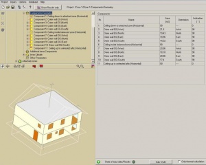
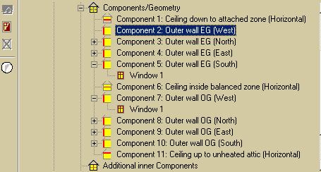
When the project building is edited with the Building Wizard or by Script file all componets are listed in the Components/Geometry elemtent. The area, the orientation and inclination are indicated.
The components are arranged by stories and orientation in the Navigation Tree and can be selected here with a double click for entering the necessary inputs.
Single Component
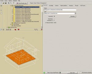
The inputs for the single components can be entered here. In the different tab layer the assebly, the surface and initial conditions for the component are to define. You may name the component well defined.
After the calculation you can see the reluts concerning only this component in the tab layer Results.
Component with Window
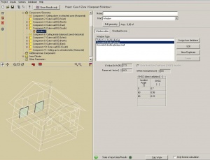
Either with a right click on the component or a klick on the New window button a window can be inserted.
The geometry of the window can be edited easy by defining position and dimension.
Then the window is to assign with the according window type. A few window types are already default but can be changed easy. Or a new window type can be defined.
In tab layer shading device you may enter the data of any available shading devices like shading factor or mode of operation.
Additional Inner Components
In the Additional inner components layer you can add components inside your heated space. For exaple walls inside the balaced zone. These components can be edit in this dialog. Similar to the compontents of the geometry you can define General Data like the denomination and the area of the additional component. The assembly can be chosen as well as surface deatils. Also the initial conditions and the numeric settings can be done. And as in the other components you can give out the specific results for the additional component after calculation in tab layer Results.
Inner Climate
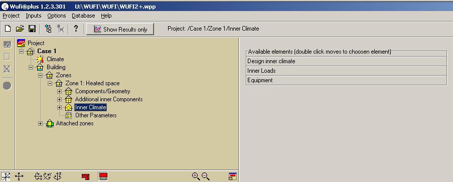
The following elements are available and to choose per double click
Design Conditions
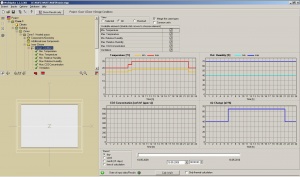
Design Conditions consists of the
- Temperature min. and max
- Relative Humidity min. and max.
- CO2-Concentration max.
- Ventilation
For this layer you have different possibilities to view. You can select a view of all parameters, of one selected or of those which are checked in the checkbox. On the bottom you can define the shown period and fix a specific date in the calculation time.
With a double click in the list of available elements you get to the choosen element.
Min. / Max. Temperature
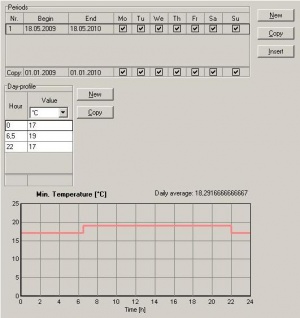
In the layers of min. and max temperature you can define the temperature profile of the building. On top you can edit periods of different temperature profiles during the year.
Beneath you can define the day-profiles for the different periods. The day can be devided in sections of variable temperatures.
The day-temperature-profile is shown as a graph at the end.
Min. / Max. Relative Humidity
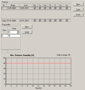
In the layers of min. and max relative humidity you can define the humidity profile of the building. On top you can edit periods of different humdidity profiles during the year.
Beneath you can define the day-profiles. The day can be devided in sections of variable percentages.
The day-profile is shown as a graph at the end.
Max. CO2-Concentration
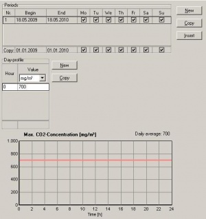
In the layers of max CO2-Concentration you can define the CO2 profile of the building. On top you can edit periods of different CO2 profiles during the year.
Beneath you can define the day-profiles. The day can be devided in sections of variable concentrations. Here you can choose from different units of the concentration.
The day-profile is shown as a graph at the end.
Ventilation
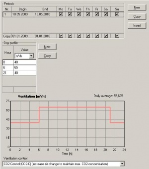
In the layer of ventilation you can define the ventilation profile of the building. On top you can edit periods of ventilation profiles during the year.
Beneath you can define the day-profiles. The day can be devided in sections of different volumes. Here you can choose from different units of the volumes.
The day-profile is shown as a graph at the end.
In the layer ventilation you can also choose the mode of ventilation control. You can select CO2-, relative Humidity- or Temperature control as well as no control.
Loads
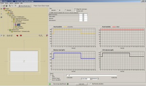
Loads consists of the
- Occupancy
- Additional
- Heat convective
- Heat radiant
- Moisture
- CO2-emission
For this layer you have different possibilities to view. You can select a view of all parameters, of one selected or of those which are checked in the checkbox. On the bottom you can define the shown period and fix a specific date in the calculation time.
Occupancy
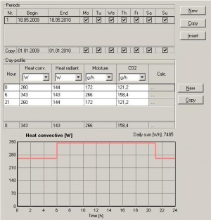
In the layer Occupancy you can define the profile of loads by occupancy in the building. On top you can edit periods of different profiles during the year.
Beneath you can define the day-profiles. The day can be devided in sections of variable occupancy. Per click on the button in coloumn Calc. you open the calculator for inner sources. Three specifications with the corresponding values for heat convective and radiant, for moisture and for CO2 are already set. With entering the count of according occupancy the total sum gets updated and transfered to the day-profile table.
The day-profile is shown as a graph at the end. It is possible to change the units for heat, moisture and CO2.
Additional

In layer additional you see a list with the additional loads you can enter. With a double click in the list of available elements you get to the choosen element.
Heat convective / Heat radiant / Moisture / CO2-Emission
Here you can enter data about additional convective heat, radiant heat, moisture or CO2-Emission. As in the other layers within the inner climate you can define periods with different loads over a year. Also you can define a day-profile for the individual periods of a year. You may select a value for the loads.
Beneath you can see the day-profile in a graph.
-
Heat convective
-
Heat radiant
-
Moisture
-
CO2-emission
Equipment
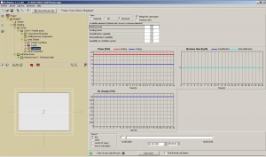
Equipment consists of the
- Heating power
- Cooling power
- Humidification capability
- Dehumidification capability
- Capability of ventilation system
For this layer you have different possibilities to view. You can select a view of all parameters, of one selected or of those which are checked in the checkbox. On the bottom you can define the shown period and fix a specific date in the calculation time.
Heating power / Cooling power / Humidification capability / Dehumidification capability
In the layers of Heating power, Cooling power, Humidification capability and Dehumidification capability you can define the periods of different heating, cooling, humidification and dehumidification over the year.
Beneath you can define the day-profiles within the periods. The day can be devided in sections of different profiles.
The day-profile is shown as a graph at the end.
-
Heating power
-
Cooling power
-
Humdification capability
-
Dehumidification capability
Capability of ventilation system
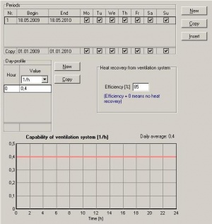
In this layer it is similar to the other equipment layer. There is one additional input. You can insert the percentage of the heat recovery from the ventilation system of the building.
Other Parameters
The other parameters are on the one hand the inital conditions in the room. Values for temperature, relative humidity and CO2 concentration have to be entered.
Further you have to select if the distribution of solar gains to the inner surface is proportional to area or user defined. You select with a click.
At last the accuracy of calculation must be appointed.
