Passive:First Steps: Unterschied zwischen den Versionen
SebSta (Diskussion | Beiträge) |
SebSta (Diskussion | Beiträge) |
||
| (14 dazwischenliegende Versionen von 2 Benutzern werden nicht angezeigt) | |||
| Zeile 1: | Zeile 1: | ||
'''Example Case'''<br> | '''Example Case'''<br> | ||
This example will give you an easy step by step guide | This example will give you an easy step by step guide on how to input a new case in WUFI®Passive. It will be a very easy case and is inspired by [http://www.wufi-wiki.com/wufifilme/flash/introduction.swf the introduction movie]. For more advanced stuff, go to the [[Passive:Input|advanced example]]. | ||
== Step Zero: Case 1 == | == Step Zero: Case 1 == | ||
| Zeile 8: | Zeile 8: | ||
== Step One: Climate and Localization == | == Step One: Climate and Localization == | ||
[[Bild:Passive-example_climate.png|Figure 2: Climate|right|thumb|Figure 2: Climate]] | [[Bild:Passive-example_climate.png|Figure 2: Climate|right|thumb|Figure 2: Climate]] | ||
WUFI Passive's | WUFI Passive's standard climate is the German reference climate as in DIN 4108-6 but we will use a different climate, in our case it will be from Hannover. To input a new climate dataset select the "user defined" scope and press the browse button. After you input valid data, the climate tab will display [[Passive2:Dialog_Climate#Climate|information]] for temperature and radiation. | ||
Remember that WUFI®Passive needs a special format of climate files which you can see | Remember that WUFI®Passive needs a special format of climate files which you can see in the previous link or in this [http://www.wufi-wiki.com/wufifilme/flash/climate_data_input.swf movie].<br> | ||
<br style="clear:both"> | <br style="clear:both"> | ||
== Step Two: Building geometry == | == Step Two: Building geometry == | ||
There are 3 ways to define a building in WUFI®Passive, the easiest one being the [[Plus_2.X:Building#Building_Wizard|building wizard]] for very simple buildings or spaces. The two | There are 3 ways to define a building in WUFI®Passive, the easiest one being the [[Plus_2.X:Building#Building_Wizard|building wizard]] for very simple buildings or spaces. The other two ways are [[Plus_2.X:Building#Edit_3D|vertices]] and [[Passive:Sketch-Up|Sketchup]], which work way better if you want to build a more complex building.<br> | ||
For our example we will use a simple room with an unheated attic and a slab on grade | For our example we will use a simple room with an unheated attic and a slab on grade. | ||
[[Bild:Passive-example building.png|center|1000px|Building wizard and orientation]] | [[Bild:Passive-example building.png|center|1000px|Building wizard and orientation]] | ||
We will add 4 windows on the south | We will add 4 windows on the south facade using the visualization box in the bottom left corner. Click the orange boxed "Windows/openings" button and a new page will appear. Click the green boxed button "Edit List" and insert the windows as seen in the picture. | ||
[[Bild:Passive-example_windows.png|center|1000px|How to input windows]] | [[Bild:Passive-example_windows.png|center|1000px|How to input windows]] | ||
Be aware that the coordinate system of the chosen wall starts in the bottom left and the X’ – axis is the orientation of the window in horizontal direction and the Y’ – axis in vertical direction.<br> | Be aware that the coordinate system of the chosen wall starts in the bottom left and the X’ – axis is the orientation of the window in horizontal direction and the Y’ – axis in vertical direction.<br> | ||
There is also a [http://www.wufi-wiki.com/wufifilme/flash/window_input_21.swf movie] about this topic.<br> | There is also a [http://www.wufi-wiki.com/wufifilme/flash/window_input_21.swf movie] about this topic.<br> | ||
A door in the north wall can be implemented almost the same way. Turn the building in the visualization box, create a "window" just like before and afterwards right click the new element and change its properties to opaque. | |||
[[Bild:Passive-example_door.png|1000px|center|Implementation of the exterior door]] | [[Bild:Passive-example_door.png|1000px|center|Implementation of the exterior door]] | ||
To clarify this is an exterior door, click on "Component 5" in the tree (if you are looking at the door in the visualization box, it will be red edged) and make a check on the "exterior door" option. | To clarify this is an exterior door, click on "Component 5" in the tree (if you are looking at the door in the visualization box, it will be red edged) and make a check on the "exterior door" option. | ||
== Step Three: Options for the passive house == | == Step Three: Options for the passive house == | ||
Next click on the "PH case:" section on the tree. Per default its value is "residential" and we will not change | Next click on the "PH case:" section on the tree. Per default its value is "residential" and we will not change anything in the "General" tab here. Instead we will go to "Additional data" and input the values boxed in blue in the picture. | ||
[[Bild:Passive-example ph case.png|center|frame|Only two values are needed here]] | [[Bild:Passive-example ph case.png|center|frame|Only two values are needed here]] | ||
Other than that we will not change any | Other than that we will not change any standard values. We will proceed to the next section: "Foundation interface" where we will fill in additional values. | ||
[[Bild:Passive-example_foundation.png|center|frame|Again only two values]] | [[Bild:Passive-example_foundation.png|center|frame|Again only two values]] | ||
== Step Four: Zonal data == | == Step Four: Zonal data == | ||
In this section we will define the [http://www.wufi-wiki.com/wufifilme/flash/tfa_example.swf | In this section we will define the [http://www.wufi-wiki.com/wufifilme/flash/tfa_example.swf TFA] and the gross volume of our building. In the green box we define the specific heat capacity of our wall; in this case our wall is massive. | ||
[[Bild:Passive-example_zone1.png|center|frame|Zonal values]] | [[Bild:Passive-example_zone1.png|center|frame|Zonal values]] | ||
| Zeile 55: | Zeile 54: | ||
{| | {| | ||
|''' Material''' | |''' Material''' | ||
| '''λ''' | | '''λ [W/mK] ''' | ||
| '''Thickness''' | | '''Thickness [m]''' | ||
|+ | |+ | ||
| ''AGEPAN DWD protect | | ''AGEPAN DWD protect | ||
| ''0,082 | | ''0,082 | ||
| ''0,016 | | ''0,016 | ||
|- | |- | ||
| ''Mineral Wool (heat cond.: 0,04 W/mK) | | ''Mineral Wool (heat cond.: 0,04 W/mK) | ||
| ''0,04 | | ''0,04 | ||
| ''0,05 | | ''0,05 | ||
|- | |- | ||
| Oriented Strand Board (density 615 kg/m³) | | Oriented Strand Board (density 615 kg/m³) | ||
| 0,13 | | 0,13 | ||
| 0,015 | | 0,015 | ||
|- | |- | ||
| Mineral Wool (heat cond.: 0,04 W/mK) | | Mineral Wool (heat cond.: 0,04 W/mK) | ||
| Zeile 77: | Zeile 76: | ||
| Oriented Strand Board (density 615 kg/m³) | | Oriented Strand Board (density 615 kg/m³) | ||
| 0,13 | | 0,13 | ||
| 0,015 | | 0,015 | ||
|- | |- | ||
| Gypsum Board | | Gypsum Board | ||
| Zeile 86: | Zeile 85: | ||
In the second layer of mineral wool more wooden beams are inserted. This time add three horizontal divisions with the dimensions 0,03 , 0,37 and 0,03. Fill in the spruce in both small gaps.<br> | In the second layer of mineral wool more wooden beams are inserted. This time add three horizontal divisions with the dimensions 0,03 , 0,37 and 0,03. Fill in the spruce in both small gaps.<br> | ||
Back in the WUFI window, you have to assign the assembly to the respective component. The assign button is right beneath the edit button we used before.<br> | Back in the WUFI window, you have to assign the assembly to the respective component. The assign button is right beneath the edit button we used before.<br> | ||
You can also use predefined or save your own assemblies [[Passive:Menu_and_Dialogues#Database:|here]] or by clicking the "Select from database" button right next to the "Edit" button we used earlier. This comes in handy | You can also use predefined or save your own assemblies [[Passive:Menu_and_Dialogues#Database:|here]] or by clicking the "Select from database" button right next to the "Edit" button we used earlier. This comes in handy if you want to use the same assembly at different projects.<br><br> | ||
Now it is time to define the other components as well; | Now it is time to define the other components as well; | ||
| Zeile 165: | Zeile 164: | ||
In this simple building, there is only one interior wall. Click on the "Not visualized components" part of the tree and input the data as seen in the picture below. | In this simple building, there is only one interior wall. Click on the "Not visualized components" part of the tree and input the data as seen in the picture below. | ||
[[Bild:Passive-example_notvis_components.png|1000px|center|Not visualized components]]<br> | [[Bild:Passive-example_notvis_components.png|1000px|center|Not visualized components]]<br> | ||
For advanced users: It is also possible to change its orientation and inclination as well as the attached zones. If doing the | For advanced users: It is also possible to change its orientation and inclination as well as the attached zones. If doing the latter, this component has to be defined the same way as the visualized components. | ||
== Step Seven: Inner Loads == | == Step Seven: Inner Loads == | ||
[[Bild:Passive-example_inner_loads.png|right|thumb|Inner loads with respective values]] | [[Bild:Passive-example_inner_loads.png|right|thumb|Inner loads with respective values]] | ||
The next step is the implementation of inner loads. | The next step is the implementation of inner loads. Click on the "Inner Loads/Occupancy" section in the tree and add the following appliances with its data into the list: | ||
{| | {| | ||
| '''Appliance ''' || '''Quantity ''' || '''Energy demand[kWh/use] or [kWh/day] '''|| ''' Additional Info ''' | | '''Appliance ''' || '''Quantity ''' || '''Energy demand[kWh/use] or [kWh/day] '''|| ''' Additional Info ''' | ||
|- | |- | ||
| Kitchen - dishwasher || 1 || 1,1 || DHW | | Kitchen - dishwasher || 1 || 1,1 || DHW connection | ||
|- | |- | ||
| Kitchen - fridge/freeze combo || 1 || 1,2 || - | | Kitchen - fridge/freeze combo || 1 || 1,2 || - | ||
| Zeile 183: | Zeile 182: | ||
| Laundry - Dryer || 1 || 3,5 || Remaining Dampness: 40 / Clothesline | | Laundry - Dryer || 1 || 3,5 || Remaining Dampness: 40 / Clothesline | ||
|} | |} | ||
WUFI also has a | WUFI also has a standard dataset with different settings as well as the possibility to input completely different appliances with a "user defined" option. | ||
<br style="clear:both"/> | <br style="clear:both"/> | ||
==Step Eight: Implementing the ventilation == | ==Step Eight: Implementing the ventilation == | ||
In this section | In this section different utilization patterns may be set up to assign to each room. In this case only one pattern will be defined and then used on every room. Click on the "New" button and then input the ventilation pattern as seen on the picture. | ||
[[Bild:Passive-example_ventilatiopn.png|center|Adding a new ventilation pattern]] | [[Bild:Passive-example_ventilatiopn.png|center|Adding a new ventilation pattern]] | ||
To apply this pattern to each room, click on the "Rooms ventilation" tab and then add four rooms | To apply this pattern to each room, click on the "Rooms ventilation" tab and then add four rooms: one kitchen, bathroom, shower and WC by pressing the "New" button on the right and then choosing the respective scope in the "Room type" section or just click on the "Standard dataset" button (boxed green). Then chose the desired pattern for each room in the "Utilization pattern" section of the table, in this case "Pattern 1: Example pattern".<br> | ||
Each room has a predefined value of exhaust air of the design volume flow rate | Each room has a predefined value of exhaust air of the design volume flow rate, but for this example use the values for exhaust and supply air as seen in the picture. To design a balanced system, the total of the supply air should equal the total of the exhaust air. | ||
[[Bild:Passive-example_ventilation_distribution.png|center|1000px|Distribution of the ventilation]] | [[Bild:Passive-example_ventilation_distribution.png|center|1000px|Distribution of the ventilation]] | ||
Each room has its own "Additional data" section where the area of the room and its clear room height | Each room also has its own "Additional data" section where the area of the room and its clear room height may be added. For this example, use the values as seen in the table below: | ||
{| | {| | ||
| || '''Kitchen ''' || '''Bathroom ''' || '''Shower ''' || ''' WC ''' | | || '''Kitchen ''' || '''Bathroom ''' || '''Shower ''' || ''' WC ''' | ||
| Zeile 200: | Zeile 199: | ||
| '''Clear room height[m] '''|| 2,5 || 2,5 || 2,5 || 2,5 | | '''Clear room height[m] '''|| 2,5 || 2,5 || 2,5 || 2,5 | ||
|} | |} | ||
The last step regarding ventilation will be to add | The last step regarding ventilation will be to add mechanical ventilation during summer. Therefore, click on the "Summer ventilation" tab and input a 0,3 ACH as seen in the picture. | ||
[[Bild:Passive-example_summer_ventilation.png|center|1000px|Settings for summer ventilation]] | [[Bild:Passive-example_summer_ventilation.png|center|1000px|Settings for summer ventilation]] | ||
| Zeile 207: | Zeile 206: | ||
[[Bild:Passive-example_thermal_bridge.png|center|1000px| Implementation of thermal bridges]] | [[Bild:Passive-example_thermal_bridge.png|center|1000px| Implementation of thermal bridges]] | ||
== Step Ten: | == Step Ten: Connection with the unheated attic == | ||
For simplicity of this example, the attic is unheated and | For simplicity of this example, the attic is unheated and non-vented but does have a temperature difference reduction factor of 75%. | ||
[[Bild:Passive-example_unheated_attic.png|center| | [[Bild:Passive-example_unheated_attic.png|center|Changing the heat reduction factor of the unheated attic]] | ||
== Step Eleven: Adding the HVAC systems == | == Step Eleven: Adding the HVAC systems == | ||
[[Bild:Passive-example_HVAC_user_defined.png|right|thumb|Choosing a predefined system or define your own]] | |||
The last thing to add is the HVAC system. WUFI®Passive allows multiple systems with different devices and also has two predefined systems, one for ventilation and one for DHW supply. In this example a user defined systems with one heat pump and one mechanical ventilation unit will be defined. The heat pump will be used for space heating and the DHW.<br> | |||
[[Bild:Passive-example_hvac_general.png|left|thumb|Two devices]]<br style="clear:both"> | |||
Next up are the settings for the heating, DHW and ventilation distribution. For both hydronic heating and the DHW the required information lie in the data of its distribution pipes. Length, design flow temperature and possible heat losses need to be defined for the pipes. The screenshots of the hydronic heating on the DHW show the required data as well as the values used in this example. | |||
<div class="tleft" style="clear:none">[[Bild:Passive-example_hvac_hydrheating.png|thumb|Hydronic heating settings]]</div> | |||
<div class="tleft" style="clear:none">[[Bild:Passive-example_hvac_dhw.png|thumb|DHW]]</div> | |||
[[Bild:Passive-example_hvac_ventilation.png|thumb|right|Ventilation]] | |||
The ventilation tab differs between exhaust and supply ducts and they both have to be defined manually. To do this press the "New" button twice and define one exhaust and one supply duct. The duct shape of both is "Round" and the supply duct length is one meter while the exhaust duct length is 3 meters. Both ducts then have to be assigned to a ventilation unit, in this case assign the "example ventilation". Next, define the duct width, insulation thickness and thermal conductivity (160,60,0,04 for both). | |||
<br style="clear:both"> | |||
To finish the HVAC systems, both devices' efficiency and assignments must be defined. For the heat pump, click on Device 1: Heat pump. For simplicity reasons, the type of the device is "heat pump". In this option only the annual coefficient of perfomance and the perfomance ratio of the heat generator must be input into WUFI®Passive. Use the values given in the picture.<br><br> | |||
The example ventilation unit requires more data, such as HRV/ERV and electric efficiency and which rooms are ventilated by it. The exact values used in this example case can also be seen in the corresponding picture.<br> | |||
<div class="tleft" style="clear:none">[[Bild:Passive-example_ventilation_unit.png|thumb|Ventilation unit]]</div> | |||
<div class="tleft" style="clear:none">[[Bild:Passive-example_heatpump.png|thumb|Heat pump]]</div> | |||
<br style="clear:both"> | |||
== Step Twelve: Getting within the passive house requirements == | |||
After performing the last steps, WUFI®Passive should give out results. If there is any necessary data missing or erroneous, WUFI will show a warning here. By double clicking on it, you jump to the cause of the error.<br> | |||
Unfortunately the results in this case will be unsatisfying regarding the heating demand and the heating load. | |||
[[Bild:Passive-example_unsatisfying.png|center|This is not what we were looking for...]] | |||
<br style="clear:both"> | |||
To solve this problem we will use a different assembly for our exterior wall: | |||
{| | |||
|'''Material''' || '''λ[W/mK]''' || '''Thickness[m]''' | |||
|- | |||
|Cement Line Plaster(stucco,A-value:2,0/m2h0.5)|| 0,8 || 0,02 | |||
|- | |||
|EPS(heat cond.: 0.04 W/mK - density: 15kg/m³) || 0,04 || 0,4 | |||
|- | |||
|Concrete, w/c=0,05 || 1,6 || 0,15 | |||
|- | |||
|Interior Plaster (Gypsum Plaster) || 0,1 || 0,015 | |||
|} | |||
And voilá: | |||
[[Bild:Passive-example_conform.png|center|Within the guidelines]] | |||
Aktuelle Version vom 10. Juni 2014, 10:19 Uhr
Example Case
This example will give you an easy step by step guide on how to input a new case in WUFI®Passive. It will be a very easy case and is inspired by the introduction movie. For more advanced stuff, go to the advanced example.
Step Zero: Case 1
In contrast to WUFI®Plus, this section does not contain any essential data but you can name your project and add some remarks.

Step One: Climate and Localization
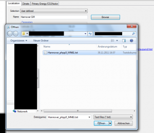
WUFI Passive's standard climate is the German reference climate as in DIN 4108-6 but we will use a different climate, in our case it will be from Hannover. To input a new climate dataset select the "user defined" scope and press the browse button. After you input valid data, the climate tab will display information for temperature and radiation.
Remember that WUFI®Passive needs a special format of climate files which you can see in the previous link or in this movie.
Step Two: Building geometry
There are 3 ways to define a building in WUFI®Passive, the easiest one being the building wizard for very simple buildings or spaces. The other two ways are vertices and Sketchup, which work way better if you want to build a more complex building.
For our example we will use a simple room with an unheated attic and a slab on grade.
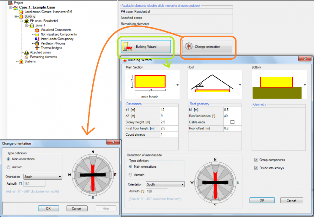
We will add 4 windows on the south facade using the visualization box in the bottom left corner. Click the orange boxed "Windows/openings" button and a new page will appear. Click the green boxed button "Edit List" and insert the windows as seen in the picture.
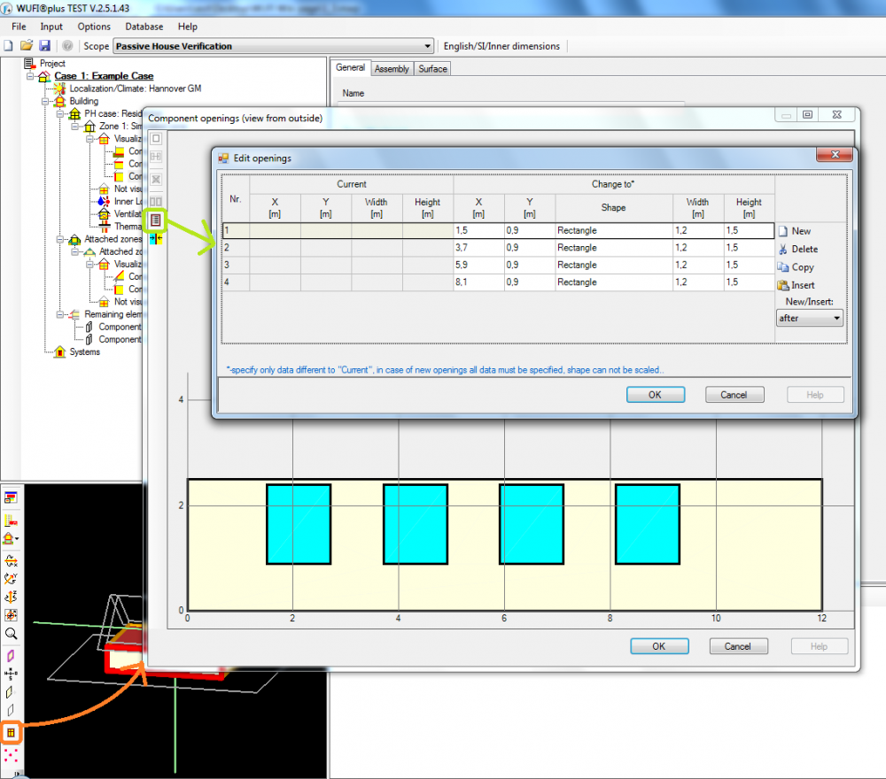
Be aware that the coordinate system of the chosen wall starts in the bottom left and the X’ – axis is the orientation of the window in horizontal direction and the Y’ – axis in vertical direction.
There is also a movie about this topic.
A door in the north wall can be implemented almost the same way. Turn the building in the visualization box, create a "window" just like before and afterwards right click the new element and change its properties to opaque.
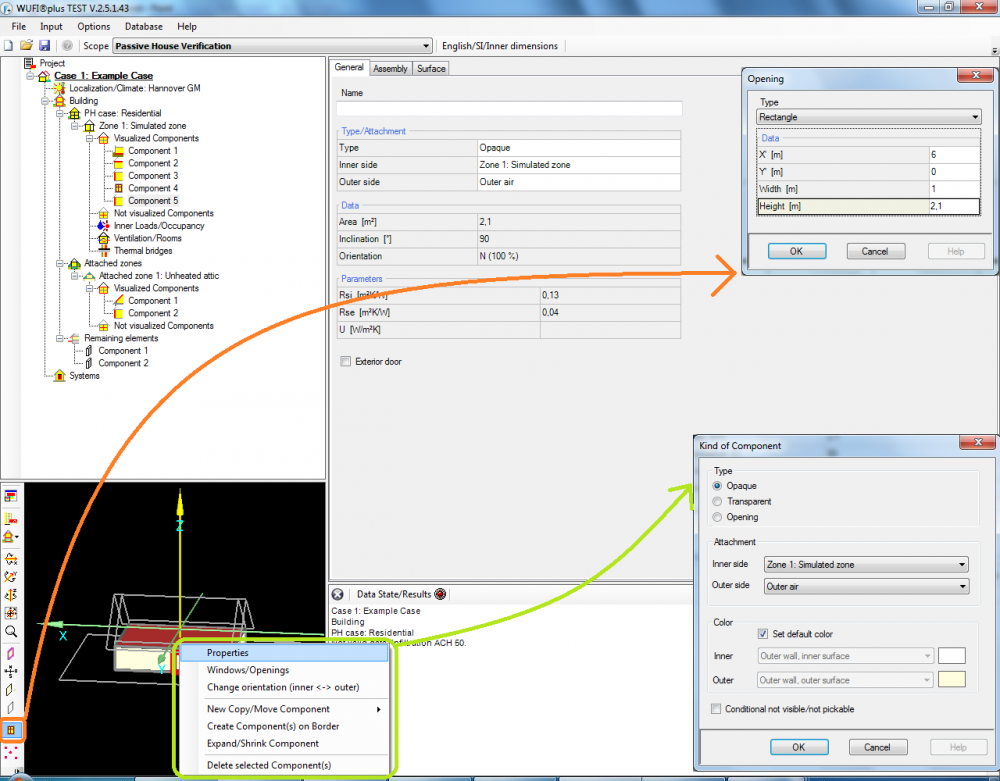
To clarify this is an exterior door, click on "Component 5" in the tree (if you are looking at the door in the visualization box, it will be red edged) and make a check on the "exterior door" option.
Step Three: Options for the passive house
Next click on the "PH case:" section on the tree. Per default its value is "residential" and we will not change anything in the "General" tab here. Instead we will go to "Additional data" and input the values boxed in blue in the picture.
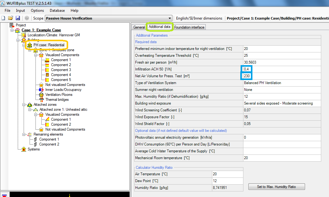
Other than that we will not change any standard values. We will proceed to the next section: "Foundation interface" where we will fill in additional values.
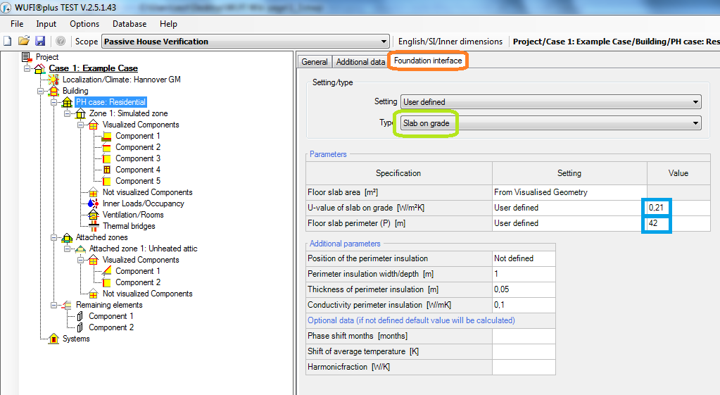
Step Four: Zonal data
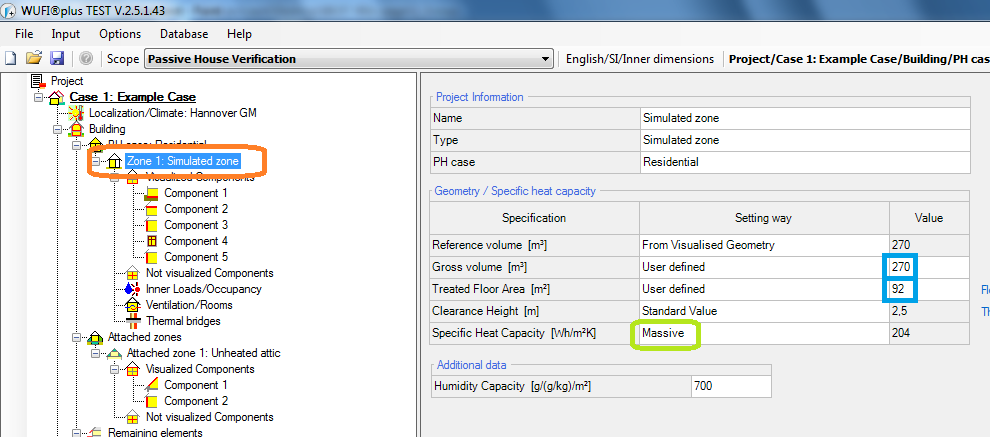
In this section we will define the TFA and the gross volume of our building. In the green box we define the specific heat capacity of our wall; in this case our wall is massive.
Step Five: Defining the components

The next subsection is all about the components and their assemblies. First we click on "Visualized components" and name each component.
Then we define the assemblies of all components and we will start with the exterior wall as described in this movie.
Therefor we click on "Component 3:ext. wall" and then on the subsection "assembly" and then on the red circled "Edit" button.
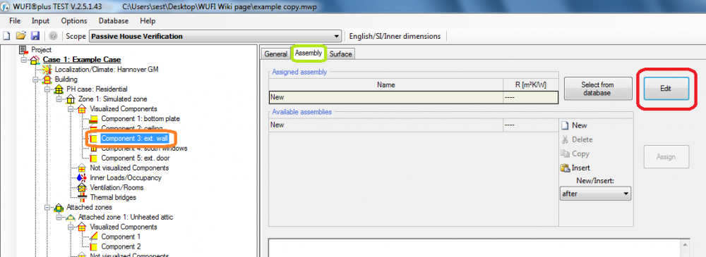
A new window will pop-up, where you can define the assembly. As seen in the video, we will construct a rear wall with wooden beams in it.
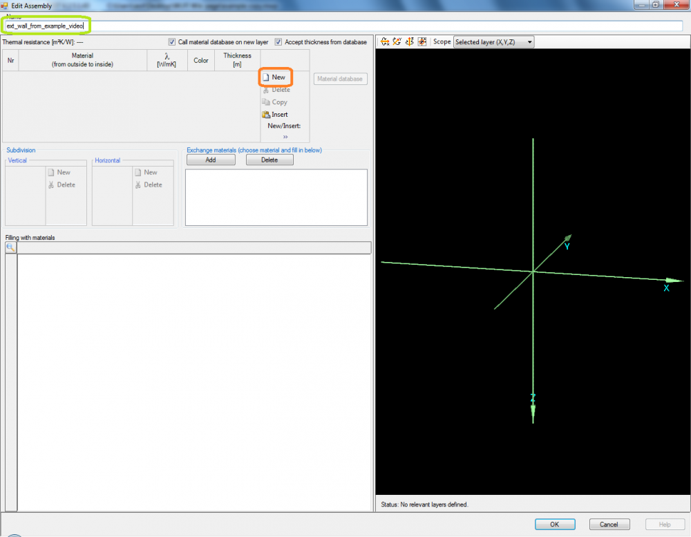
First we will name our assembly and then search for our needed materials by clicking on "New".
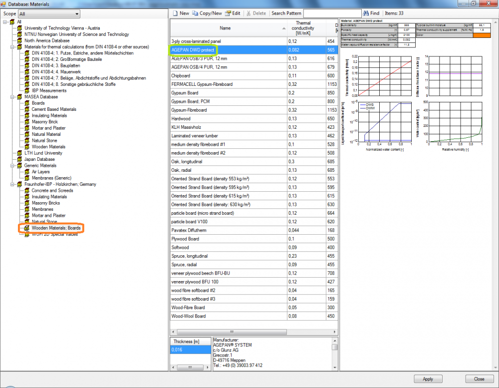
In the material database we will chose the "Wooden materials;Boards" section and define the first layer of our wall.
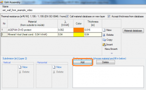
The next layer then will be an insulation material. In this layer are the interupting beams, so click on the "Add" button and you will get to the material database again. Select your beam material (in this case it is "Spruce, radial", which you can find in the "Wooden materials;Boards" section) and then the raster of the timber beams by creating new sections in the horizontal section. Then click on the spruce in the "exchange materials" box and click on the respective section as seen in the picture below.
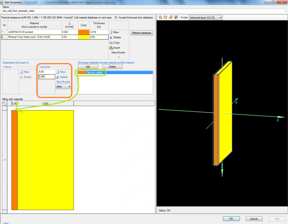
Define then the remaining layers so that the assembly consists of following materials:
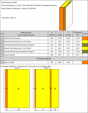
| Material | λ [W/mK] | Thickness [m] |
| AGEPAN DWD protect | 0,082 | 0,016 |
| Mineral Wool (heat cond.: 0,04 W/mK) | 0,04 | 0,05 |
| Oriented Strand Board (density 615 kg/m³) | 0,13 | 0,015 |
| Mineral Wool (heat cond.: 0,04 W/mK) | 0,04 | 0,05 |
| Oriented Strand Board (density 615 kg/m³) | 0,13 | 0,015 |
| Gypsum Board | 0,2 | 0,01 |
In the second layer of mineral wool more wooden beams are inserted. This time add three horizontal divisions with the dimensions 0,03 , 0,37 and 0,03. Fill in the spruce in both small gaps.
Back in the WUFI window, you have to assign the assembly to the respective component. The assign button is right beneath the edit button we used before.
You can also use predefined or save your own assemblies here or by clicking the "Select from database" button right next to the "Edit" button we used earlier. This comes in handy if you want to use the same assembly at different projects.
Now it is time to define the other components as well;
| Ceiling | Bottom Plate | Exterior Door | |||||||||
| Material | λ | Thickness | Material | λ | Thickness | Material | λ | Thickness | |||
| Mineral Wool (heat cond.: 0,04 W/mK) | 0,04 | 0,3 | PVC Roof Membrane | 0,16 | 0,001 | EPS (heat cond.: 0.04 W/mK - density: 30kg/m³) | 0,04 | 0,05 | |||
| Concrete, w/c=0.5 | 1,6 | 0,1 | EPS (heat cond.: 0.04 W/mK - density: 30kg/m³) | 0,04 | 0,25 | ||||||
| Concrete, w/c=0.5 | 1,6 | 0,2 |
Windows
For this example, a predefined window is used. More about implementing windows and their settings can be seen in this video.
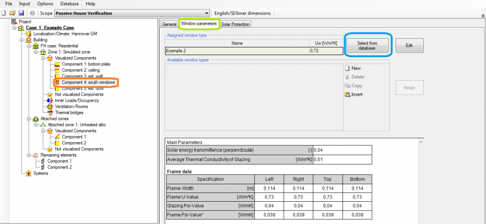
The example 2 windows are predefined windows from the WUFI®Passive database and easy to find.
Step Six: Interior Walls
In this simple building, there is only one interior wall. Click on the "Not visualized components" part of the tree and input the data as seen in the picture below.

For advanced users: It is also possible to change its orientation and inclination as well as the attached zones. If doing the latter, this component has to be defined the same way as the visualized components.
Step Seven: Inner Loads
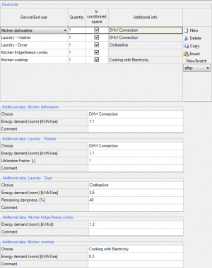
The next step is the implementation of inner loads. Click on the "Inner Loads/Occupancy" section in the tree and add the following appliances with its data into the list:
| Appliance | Quantity | Energy demand[kWh/use] or [kWh/day] | Additional Info |
| Kitchen - dishwasher | 1 | 1,1 | DHW connection |
| Kitchen - fridge/freeze combo | 1 | 1,2 | - |
| Kitchen - cooktop | 1 | 0,3 | Cooking with electricity |
| Laundry - Washer | 1 | 1,1 | DHW connection |
| Laundry - Dryer | 1 | 3,5 | Remaining Dampness: 40 / Clothesline |
WUFI also has a standard dataset with different settings as well as the possibility to input completely different appliances with a "user defined" option.
Step Eight: Implementing the ventilation
In this section different utilization patterns may be set up to assign to each room. In this case only one pattern will be defined and then used on every room. Click on the "New" button and then input the ventilation pattern as seen on the picture.
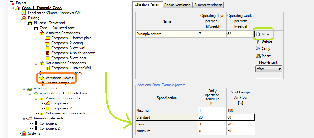
To apply this pattern to each room, click on the "Rooms ventilation" tab and then add four rooms: one kitchen, bathroom, shower and WC by pressing the "New" button on the right and then choosing the respective scope in the "Room type" section or just click on the "Standard dataset" button (boxed green). Then chose the desired pattern for each room in the "Utilization pattern" section of the table, in this case "Pattern 1: Example pattern".
Each room has a predefined value of exhaust air of the design volume flow rate, but for this example use the values for exhaust and supply air as seen in the picture. To design a balanced system, the total of the supply air should equal the total of the exhaust air.
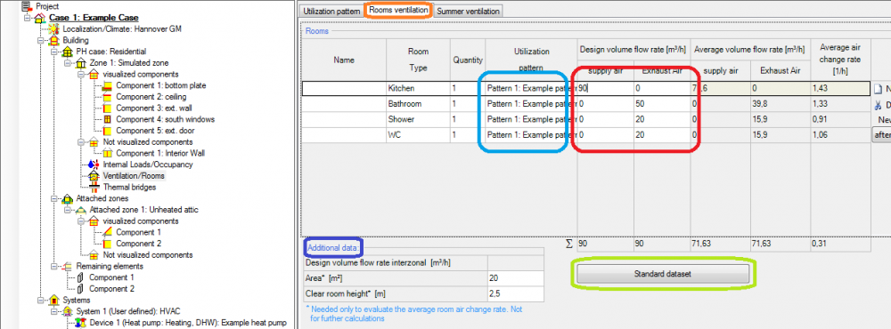
Each room also has its own "Additional data" section where the area of the room and its clear room height may be added. For this example, use the values as seen in the table below:
| Kitchen | Bathroom | Shower | WC | |
| Area [m²] | 20 | 12 | 7 | 6 |
| Clear room height[m] | 2,5 | 2,5 | 2,5 | 2,5 |
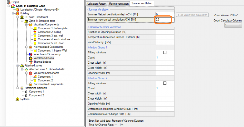
The last step regarding ventilation will be to add mechanical ventilation during summer. Therefore, click on the "Summer ventilation" tab and input a 0,3 ACH as seen in the picture.
Step Nine: Thermal Bridges
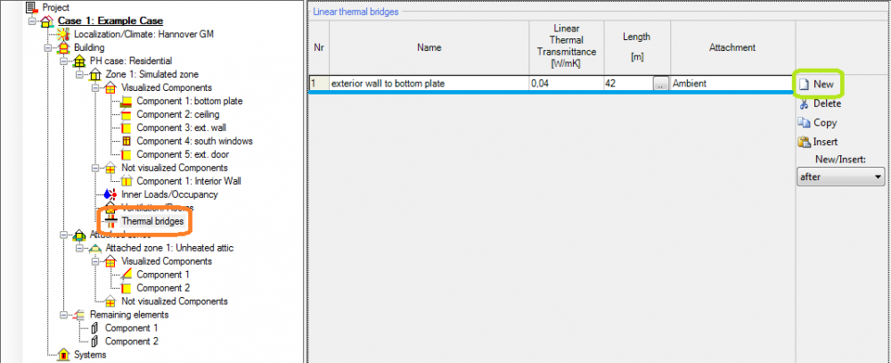
Thermal brigdes have an underestimated influence on energy performance and are found in every building. In our example building there is only one so add it by clicking on the "Thermal bridges" section in the tree and then on the "New" button on the right side. The thermal bridge has a linear thermal transmittance of 0,04 W/mK and is 42 meters long.
Step Ten: Connection with the unheated attic
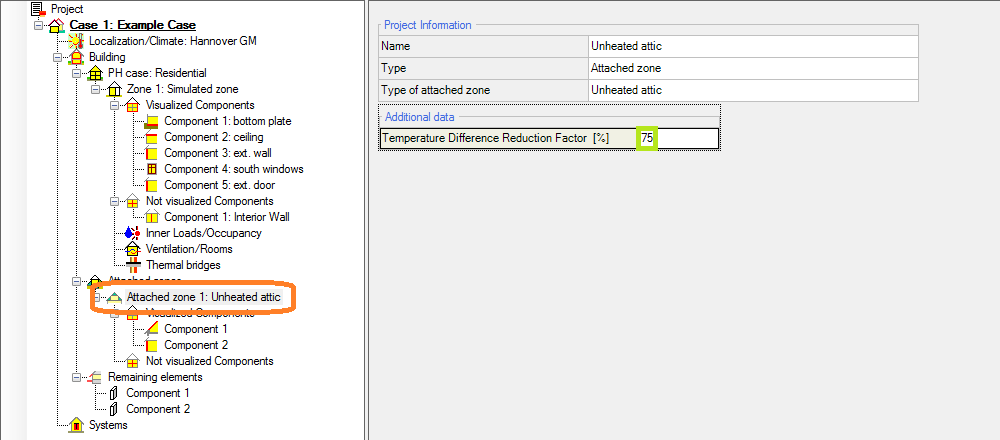
For simplicity of this example, the attic is unheated and non-vented but does have a temperature difference reduction factor of 75%.
Step Eleven: Adding the HVAC systems
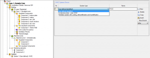
The last thing to add is the HVAC system. WUFI®Passive allows multiple systems with different devices and also has two predefined systems, one for ventilation and one for DHW supply. In this example a user defined systems with one heat pump and one mechanical ventilation unit will be defined. The heat pump will be used for space heating and the DHW.
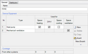
Next up are the settings for the heating, DHW and ventilation distribution. For both hydronic heating and the DHW the required information lie in the data of its distribution pipes. Length, design flow temperature and possible heat losses need to be defined for the pipes. The screenshots of the hydronic heating on the DHW show the required data as well as the values used in this example.
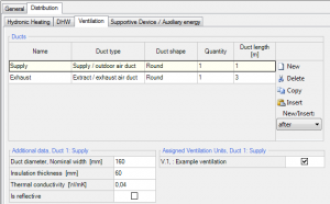
The ventilation tab differs between exhaust and supply ducts and they both have to be defined manually. To do this press the "New" button twice and define one exhaust and one supply duct. The duct shape of both is "Round" and the supply duct length is one meter while the exhaust duct length is 3 meters. Both ducts then have to be assigned to a ventilation unit, in this case assign the "example ventilation". Next, define the duct width, insulation thickness and thermal conductivity (160,60,0,04 for both).
To finish the HVAC systems, both devices' efficiency and assignments must be defined. For the heat pump, click on Device 1: Heat pump. For simplicity reasons, the type of the device is "heat pump". In this option only the annual coefficient of perfomance and the perfomance ratio of the heat generator must be input into WUFI®Passive. Use the values given in the picture.
The example ventilation unit requires more data, such as HRV/ERV and electric efficiency and which rooms are ventilated by it. The exact values used in this example case can also be seen in the corresponding picture.
Step Twelve: Getting within the passive house requirements
After performing the last steps, WUFI®Passive should give out results. If there is any necessary data missing or erroneous, WUFI will show a warning here. By double clicking on it, you jump to the cause of the error.
Unfortunately the results in this case will be unsatisfying regarding the heating demand and the heating load.

To solve this problem we will use a different assembly for our exterior wall:
| Material | λ[W/mK] | Thickness[m] |
| Cement Line Plaster(stucco,A-value:2,0/m2h0.5) | 0,8 | 0,02 |
| EPS(heat cond.: 0.04 W/mK - density: 15kg/m³) | 0,04 | 0,4 |
| Concrete, w/c=0,05 | 1,6 | 0,15 |
| Interior Plaster (Gypsum Plaster) | 0,1 | 0,015 |
And voilá:


