Plus:TreeBuilding: Unterschied zwischen den Versionen
Tes (Diskussion | Beiträge) |
Tes (Diskussion | Beiträge) |
||
| Zeile 8: | Zeile 8: | ||
=Edit 3D= | =Edit 3D= | ||
If the geometry of the building exceeds the capabilities of the Building Wizards, it can be expanded and changed in the entry window '3D Edit'. For this,zoom the window. | If the geometry of the building exceeds the capabilities of the Building Wizards, it can be expanded and changed in the entry window '3D Edit'. For this, zoom the window. | ||
[[Bild:WUFI-PlusVertices.jpg|700px]] | [[Bild:WUFI-PlusVertices.jpg|700px]] | ||
Version vom 14. Oktober 2010, 14:34 Uhr
Building Wizard
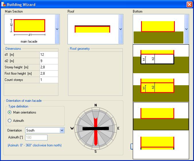
For the new project, the building can be created in two ways. Is the building or the space not too complex in its geometry the automatic building wizard can be used to generate. This tool generates automatically, with some details of floor plan, roof form and foundation the building.

Edit 3D
If the geometry of the building exceeds the capabilities of the Building Wizards, it can be expanded and changed in the entry window '3D Edit'. For this, zoom the window.
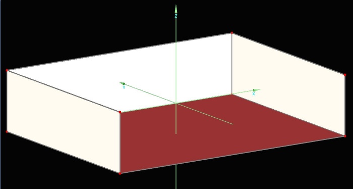
Also, a complete structure of the building simulation is possible here. By setting vertices, the geometry can be constructed and the vertices connected to components. This allows the input of complex building shapes.
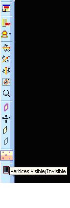
The user must switch the vertices visible.
New points can be defined by entering the coordinates. They are arbitrarily variable with operations like copy, move….. These operations are invoked on selected vertices by a right mouse click. Multiple vertices can be selected by holding CTRL.
The created vertices can then be connected to components. Select the vertices and with the operation ‘make components of selected vertices’ the new component is generated.
Openings such as windows and doors are added with a right mouse click and ‘Openings’. They appear in the navigation tree and can be edited as usual.


