Plus 2.X:Input: Unterschied zwischen den Versionen
Krizzl (Diskussion | Beiträge) Keine Bearbeitungszusammenfassung |
Krizzl (Diskussion | Beiträge) Keine Bearbeitungszusammenfassung |
||
| Zeile 62: | Zeile 62: | ||
The building must be staked out with windows as well. The following | The building must be staked out with windows as well. The following pictures show you how windows should be placed along the walls. | ||
Measurements are | |||
{| | |||
|WINDOW | |||
|length [m] | |||
|height[m] | |||
|- | |||
|a | |||
|1,2 | |||
|2,1 | |||
|- | |||
|b | |||
|1 | |||
|0,9 | |||
|- | |||
|c | |||
|3 | |||
|1 | |||
|- | |||
|} | |||
[[Bild:P2-w1.png|center|frame|1000px|Figure 7: The windows 1]]<br> | |||
[[Bild:P2-w2.png|center|frame|1000px|Figure 8: The windows 2]]<br> | |||
==Step 5: Creation of the zones== | ==Step 5: Creation of the zones== | ||
Version vom 10. August 2011, 09:17 Uhr
This case will help you immerse yourself deeper into WUFI plus. After having performed and understood it you will be a WUFI expert! Like the first (easier) case, this case is built up following the navigation tree.
This case is about modelling a house (like we did before in example 1st) with an building attachment (used as fitness studio). As it is pretty complicated and complex small movie sections come along each chapter.
It begins quite similar to our first example, so the first chapters are very much the same.
STEP one: Information and setting of Framework Conditions
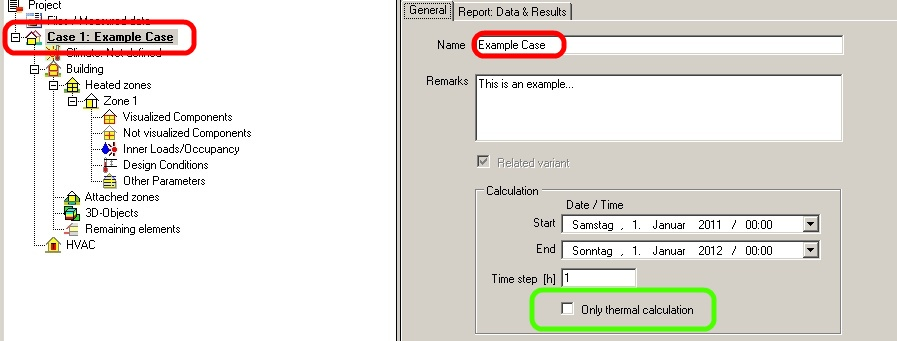
Press the “New Project” button in the Menu Bar and define a name for your project by clicking on “Case 1” in the Project Explorer. Additionally, you can enter remarks. More important is the setting of a Start and End Value as well as a suitable calculation time step like shown below in Figure 1. Furthermore, it is possible to check the entry “Only thermal calculation” (green box). Using this setting the coupled heat and moisture transport processes in the assemblies will be neglected. Only the energy transport will be considered. This will accelerate the calculation process but causes unreasonable results especially for the moisture balance as hygric interaction with assemblies is neglected. The humidity conditions inside the assemblies are not available. In our case this box will NOT be check marked.
STEP two : Definition of the climatic Conditions
Again we want to use the predefined climate of Holzkirchen, so follow step a) and b) in the picture below.

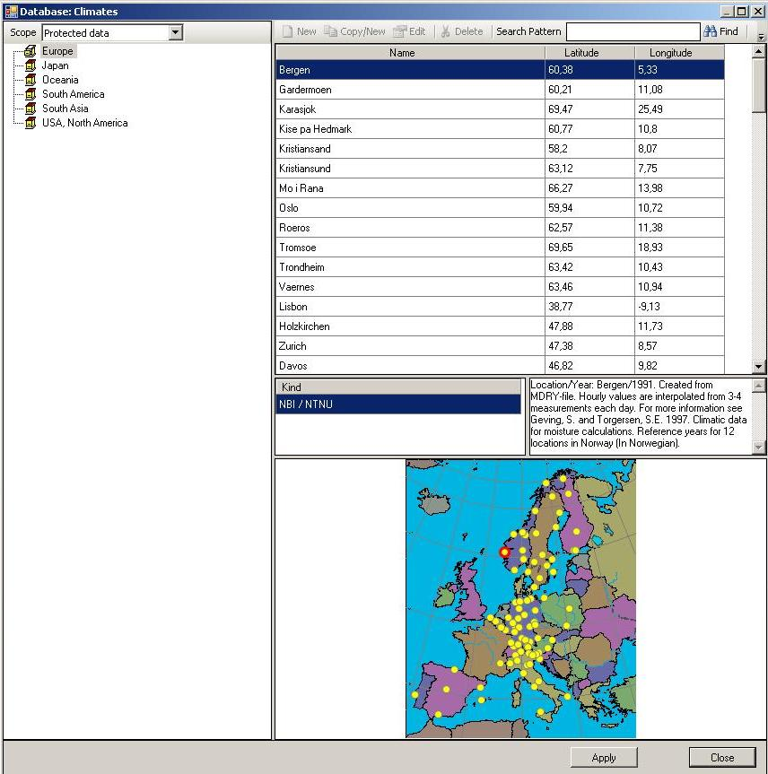
After hitting the “Browse” button another window opens (Figure 3) and the desired climate can be chosen from predefined locations by double-clicking on it.
For advanced users: It is also possible to define own climate conditions or to import own climate files.
As long as your building does not float in the air, for whatever reason, it is necessary to define at least one additional climate to give reasonable boundary conditions for the inert behavior of soil. This can be done using the “Optional Climates” tab. For the soil temperature it is accurate to select a sine curve that has its peak at about two months later than summer solstice, i.e. at the end of August / in early September in the northern hemisphere. Depending on local conditions, the amplitude of the sine curve can be modified due to the annual fluctuation of the temperature curves. This fluctuation is the difference of the mean maximum temperature of soil in warm seasons and the mean minimum temperature of soil in cold seasons. For continental climates like Siberia this amplitude may be high (high temperatures in summer, very cool winter), for maritime climate systems it is rather low. Furthermore, the mean temperature must be set. This can be approximated using the annual average air temperature. In this example we assume the climate of Holzkirchen, the WUFI’s origin with moderate continental climate. How this can be entered in WUFI®Plus can be seen in Figure 4 on the next page.
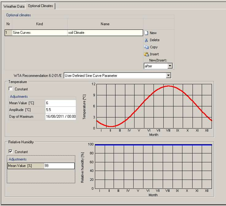
At first click at the “New” button to create a new optional climate. Then choose the sine curve and rename it to "Soil Climate" for example. In the next step choose “User Defined Sine Curve Parameter” and input following data for the temperature:
| Mean Value (°C): | 6 |
| Amplitude (°C): | 5,5 |
For relative humidity a constant mean value of 99% is adequate.
STEP three: Generating of Building Geometry
Building Wizard
Like we did before we want to use the Building Wizard to create our building. But additionally a building extension is to be added to the house using vertices.
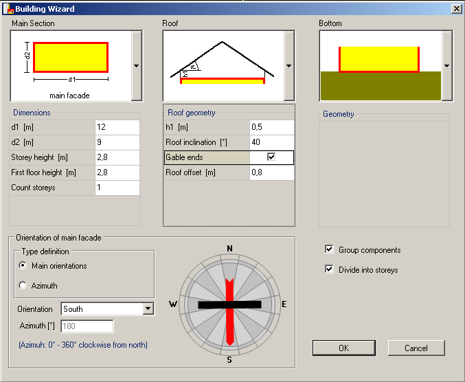
Again we assume a simple case with one heated slab-on-ground zone and an inclined unheated attic. Just enter the same inputs as in Figure 5 for you building in the Building Wizard.
Using vertices
The simple building created with the [[Plus 2.X:Building#Building Wizard|Building Wizard] shall be expanded. The building extension will serve as fitness studio. The ready building should look like shown in Figure 6.
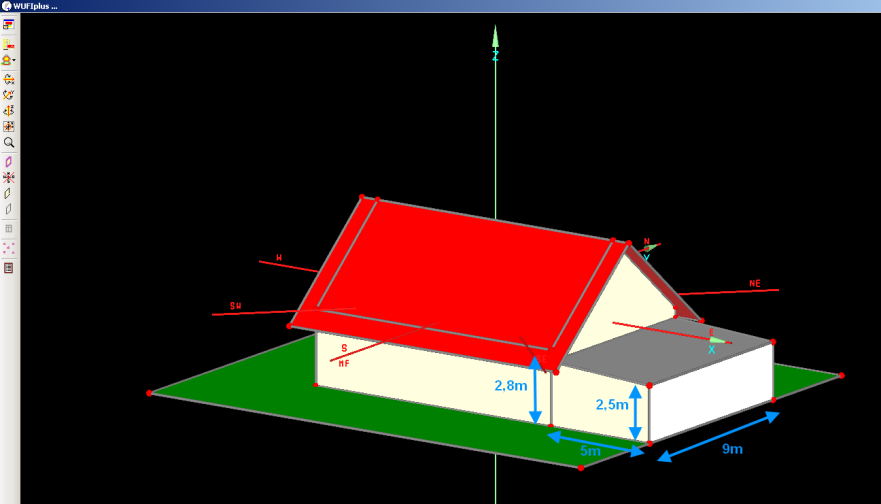
For creating it you need to work with vertices.For more information on this topic, click here. By copying and moving preexisting vertices and components and by creating new vertices and components, any desired building geometry can be generated. Of course there are several procedured to create the building extension.
One is shown in the following movie.
Step 4: Windows
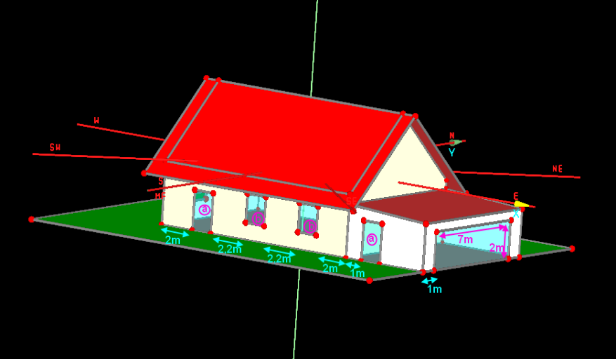
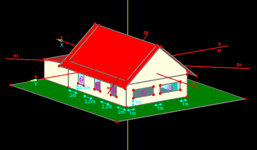
The building must be staked out with windows as well. The following pictures show you how windows should be placed along the walls. Measurements are
| WINDOW | length [m] | height[m] |
| a | 1,2 | 2,1 |
| b | 1 | 0,9 |
| c | 3 | 1 |
Step 5: Creation of the zones
zuweisen, blabla, farben