Plus:HowTo
Simulation procedure
This is a short description of a simulation procedure.
For detailed information to the several steps follow the links.
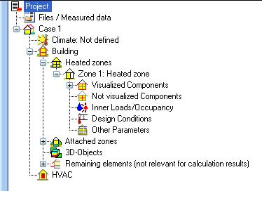
The elements in the navigation tree lead you step by step through all necessary inputs.
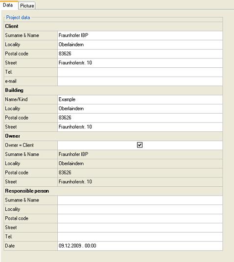
Start with the definition of the general project information.
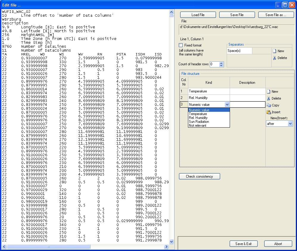
Are additional data or files are needed for the calculation, load it into the programm.
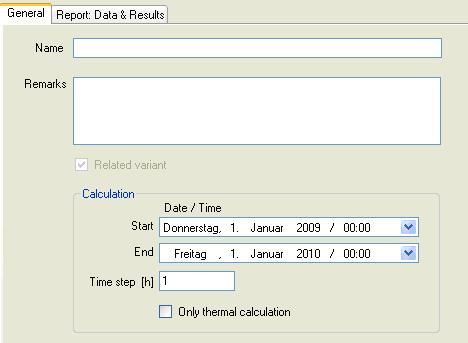
Remark all alterations and characteristics of the current case variation and define the simulation period.
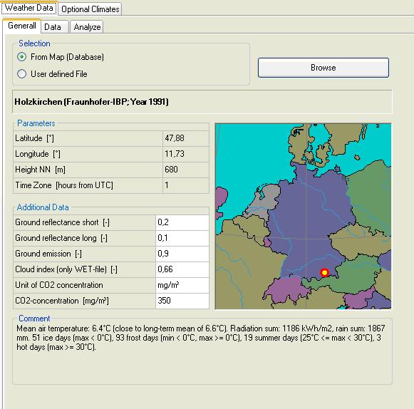
Select the boundary conditions. This can be either a climate from the WUFIplus database or user defined. Additional optional climates can be defined (e.g. ground, attached zones).
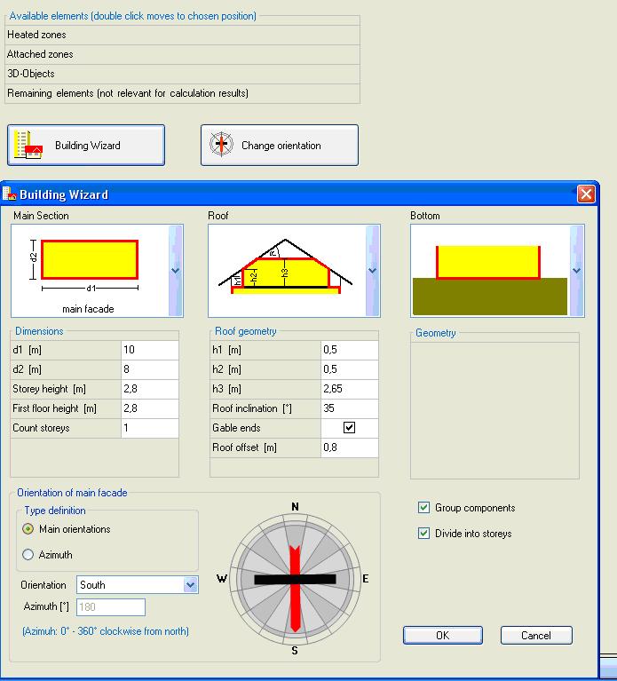
Model the simulation building.
For plain geometries use the 'building wizard' to generate the simulation envelope. For more complex geometries use the '3D editor'.
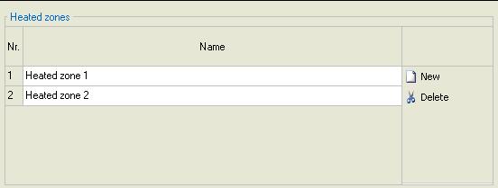
Create the several heated zones within the simulation envelope.
Make the stettings for the several zones.
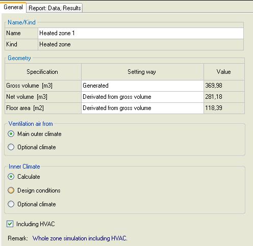
Allocate the components to the respective zone.
Define and asign the assemblies.
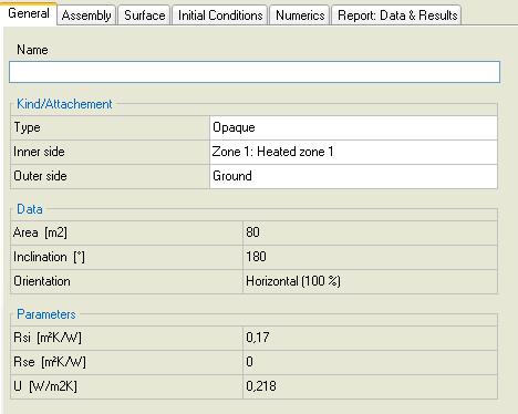
Set the parameters for surface, initial conditions and numerics.
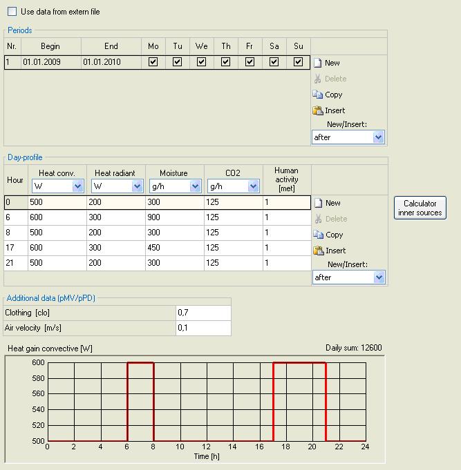
The occuring inner loads by machines or occupants can be defined in profiles by the hour.
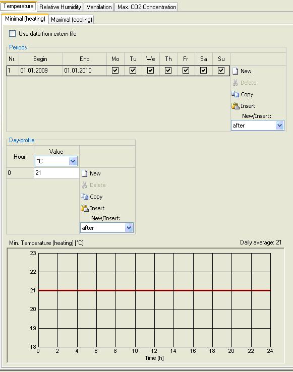
The design conditions for the zone are defined by the hour as well.
These values are setpoints for the HVAC system.
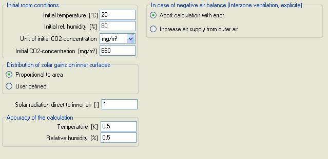
To start the calculation the initial conditions have to be defined.
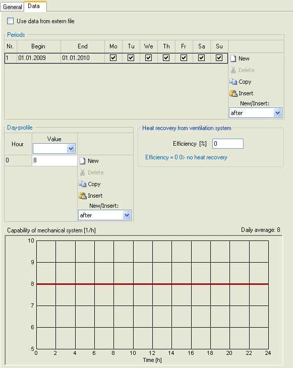
Constitute the capability of the projected HVAC system.
Calculation
The completeness of the inputs is shown in the state bar with the green button.

Results
